Create LED art installations and wearables using low cost, HUB75 based LED matrix panels. PIXEL supports installations from 32×16, 32×32, 64×32, 64×64, and 128×32 resolutions. Simply download PIXEL’s free apps for iOS, Android, or Raspberry Pi and send GIF animations, scrolling text, and your own pixel art creations in seconds, no soldering or coding required! As an added bonus, the free apps include 100+ works of original pixel art commissioned for this project.
The PIXEL:LED ART board includes an onboard microSD card allowing you to save your LED art designs locally which will loop indefinitely on the LEDs after your device has been Bluetooth disconnected. Or leave your Android or Raspberry Pi connected and custom code an interactive application displaying art or scrolling messages using our open source example code including support for external sensors (external sensors only supported on Android only firmware).
IMPORTANT: PIXEL Maker’s Kits purchased prior to February 2018 are NOT compatible with iOS and only support Android and Raspberry Pi.
By default, the PIXEL Maker’s Kit is installed with the Android only firmware which supports LED panels from 32×16 to 64×64. However, if you need iOS and/or low power wearable support, you can easily switch firmwares by copying image files to the microSD card on your PIXEL board.
| Firmware | Android | iOS | Raspberry Pi | Grove Sensors | Low Power for Wearables | Hub75 LED Panel Support (E-Pin Panels Not Supported) |
| Android & Raspberry Pi (Default) | Yes | No | Yes | Yes | No | 32×16, 32×32,64×32, 64×64 |
| iOS & Android 32×16 | Yes | Yes | No | No | Yes | 32×16 Only |
| iOS & Android 32×32 | Yes | Yes | No | No | Yes | 32×32 Only |
![]()
The PIXEL Maker’s Kit includes:
- Pixel 2.5 Board
- LED Matrix Power Cable
- A to A USB 2.0 Cable (5 feet)
- MicroSD Card
- Bluetooth CSR 4.0 USB Dongle
- External On/Off Switch
- LED Matrix IDC Ribbon Cable (9 inches)
- Free iOS, Android, and Raspberry Pi apps

Ships from California, USA

Ships from Shenzhen, China
DIY Example Projects on Instructables
- SUPER PIXEL 64×64 Art Frame
- PIXEL 32×32 Art Frame
- Arcade LED Marquee
- 32×16 Wearable
- Android Magic Mirror
- Mirror Installation
- Smart Brake Light
If you are making a portable battery powered wearable, use the iOS/Android 32×16 or iOS/Android 32×32 low power firmware image and refer to this sample wearables project for instructions.
The PIXEL Maker’s kit does not include an LED matrix panel or power supply. Choose from the following LED matrix panels of which most have been tested. Please do shoot us a note if you test one of the untested LED panels or find an additional panel and we’ll update this page for others. You can daisy chain multiple LED panels for a maximum resolution of 64×64 or 4096 LEDs.
IMPORTANT: PIXEL is designed to work with HUB75 based LED matrix panels. HUB75 is a LED panel standard which includes a standard 16-pin IDC connector. But various HUB75 manufacturers implement different pixel ordering which may or may not be compatible with the PIXEL Maker’s Kit. Therefore, it’s highly recommended to only purchase tested LED panels from the list below. Ordering direct from China from sites like Aliexpress will be much cheaper but not feasible for returns should the LED panel not be compatible.
The P number is the pitch or the distance from the center of one LED to the next. P6 is 6mm, P4 is 4mm, P3 is 3mm, etc. P3 would be the most dense / smallest display and P10 the least dense / largest display. All LED panels use the HUB75 standard.
Note that while the connector looks the same, HUB75E (with an extra E-pin), HUB08, and HUB12 (single color) panels will not work. WS28XX / neopixels LED strips are also not compatible. HUB75 panels specifically with the FM6126A LED driver chipset will not work.
IMPORTANT: As of Jan’ 2019, some suppliers are offering a different panel based on the FM6126A chipset, this chipset will not work with PIXEL. Also the chipset ICN2028 is also not compatible. ICN2037 and JXI5020 chipsets are known to work with PIXEL.
Note: When ordering from AliExpress, always check with the supplier first (you can use AliExpress Chat) and verify the chipset is ICN2037 or JXI5020 and that the panel is HUB75 and not HUB75E.
| LED Matrix Panel | Dimensions | Result | Power | Notes |
| p10 / 10mm Pitch | ||||
| JS Industrial 32×16 P10 1/8 Scan | 320mm x 96 mm x 12 mm/ 12.6″ x 6.3″ x .5″ | Pass | 5V, 2A | Can daisy chain for 64×16, good size for scrolling messages. Use the low power firmware for portable applications. |
| P6 / 6mm Pitch | ||||
| Adafruit 32×16 P6 1/8 scan | 192mm x 96mm x 12mm / 7.6″ x 3.8″ x 0.5″ | Pass | 5V, 2A | Can daisy chain for 64×16, good size for scrolling messages. Use the low power firmware for portable applications. |
| Adafruit 32×32 P6 | 190.5mm x 190.5mm x 14mm / 7.5″ x 7.5″ x 0.55″ | Pass | 5V, 4A or 5V, 20A for 4 daisy chained | Can daisy chain for 64×32 or 64×64 |
| RGX 32×32 P6 | 192*192mm | Pass | 5V, 4A or 5V, 20A for 4 daisy chained | Can daisy chain for 64×32 or 64×64 |
| Adafruit 64×32 P6 1/16 scan | 385mm x 190mm x 13mm / 15.2” x 7.5” x 0.5” | Not Tested | 5V, 10A | Not tested but should work. Can daisy chain for 64×64 |
| P5 / 5mm Pitch | ||||
| Seeedstudio 32×32 P5 | 160mm x 160mm / 6.3″ x 6.3″ | Not Tested | 5V, 4A | Not tested but should work |
| Adafruit 64×32 P5 | 318mm x 158mm x 15mm / 12.5” x 6.2” x 0.6” | Not Tested | 5V, 10A | Not tested but should work. Can daisy chain for 64×64 |
| eBay 64×32 P5 | 318mm x 158mm x 15mm / 12.5” x 6.2” x 0.6” | Pass | 5V, 10A | Can daisy chain for 64×64 |
| JS Industrial 64×64 P5 1/16 Scan | 320mm x 320mm x 15mm / 12.6″ x 12.6″ x .6″ | Pass | 5V, 20A | |
| Amazon Germany Azerone 64×32 P5 | 320mm x 160mm | Pass | 5V, 20A | |
| P4 / 4mm Pitch | ||||
| Amazon Azerzone 64×32 (Flexible) | 256mm x 128mm | Pass | 5V, 10A | 2/28/2019, ordered on Amazon, 15 days shipping from China, flexible panel |
| Seeedstudio 64×32 P4 | 256mm x 128mm | Not Tested | 5V, 10A | Not tested but should work. Can daisy chain for 64×64 |
| Adafruit 32×32 P4 1/16 scan | 128mm x 128mm x 17mm / 5.0″ x 5.0″ x 0.65″ | Not Tested | 5V, 4A | Not tested but should work. Can daisy chained for 64×32 or 64×64 |
| Meiyad 32×32 P4 | 128mm x 128mm x 17mm / 5.0″ x 5.0″ x 0.65″ | Pass | 5V, 4A | Meiyad is a Shenzhen, China LED Panel Manufacturer |
| NovaeLED P4 | Fail | Image garbled, pixel ordering is off | ||
| P3/ 3mm Pitch | ||||
| Amazon 64×32 P3 | 191mm x 96mm x 15mm / 7.5” x 3.8” x 0.6” | Pass | 5V, 4A or 5V, 10A for 2 daisy chained | Can daisy chain for 64×64. Video of 64×64 P3 vs. P6 |
| SRYLED 64×32 P3 AliExpress | 91mm x 96mm x 15mm / 7.5” x 3.8” x 0.6” | Pass | 5V, 4A or 5V, 10A for 2 daisy chained | In the order notes on AliExpress, do specify panel should not have an “E” pin
Can daisy chain for 64×64. Video of 64×64 P3 vs. P6 |
| AliExpress 64×32 P3 | 191mm x 96mm x 15mm / 7.5” x 3.8” x 0.6” | Pass | 5V, 4A or 5V, 10A for 2 daisy chained | Can daisy chain for 64×64. Video of 64×64 P3 vs. P6 |
| Adafruit 64×32 P3 | 191mm x 96mm x 15mm / 7.5” x 3.8” x 0.6” | Pass | 5V, 4A or 5V, 10A for 2 daisy chained | Tested and Works. Can daisy chain for 64×32 or 64×64. Video of 64×64 P3 vs. P6 |
| Meiyad 64×64 P3 | Fail | 5V, 10A | Did not display correctly, panels with the “E” pin will not work | |
| Yao Cai Xing 64×32 P3 AliExpress | 192mm x 96mm | Fail | 2/28/19 – FM6126A LED Driver Chipset, LEDs don’t turn on, details why FM6126A does not work | |
| P2.5/2.5mm PItch | ||||
| SRYLED P2.5 64×32 AliExpress | 160mm x 80 mm | Pass | 5V, 4A | The blue and green color channels are crossed. You’ll need to select the P2.5 matrix type in the Android app or API app for the colors to show correctly. |
| 64×64 P2.5 AliExpress | 160mm x 160mm | Pass | 5V, 10A | Aliexpress, IMPORTANT: When ordering, specify 1/16 scan and HUB75 in your order notes or you may get 1/32 scan and HUB75E which is not compatible with PIXEL. |
Daisy Chaining Wiring Diagrams
IMPORTANT: The 4 pin LED matrix power connector on the PIXEL board can only be used to power one 32×32 panel as the DC jack connector on the PIXEL board cannot handle the current draw of multiple 32×32 panels. When powering more than 32×32, wire power to the LED matrices still from the same power supply but not through the PIXEL board.
| Two 64x32s = 64×64 (use this for the 64×64 panel too) In addition to the kit, you’ll need:2 IDC 16-pin ribbon cables (female connectors on both ends) at least 19″ long, and a 5V/20 power supply (see options below). The LED panels you purchase will come with the 4-pin LED power connectors. But you will need to splice the wires yourself per the diagram to the right. IMPORTANT: Follow the wiring diagram and ensure the LED panels are not getting power through the PIXEL board. | 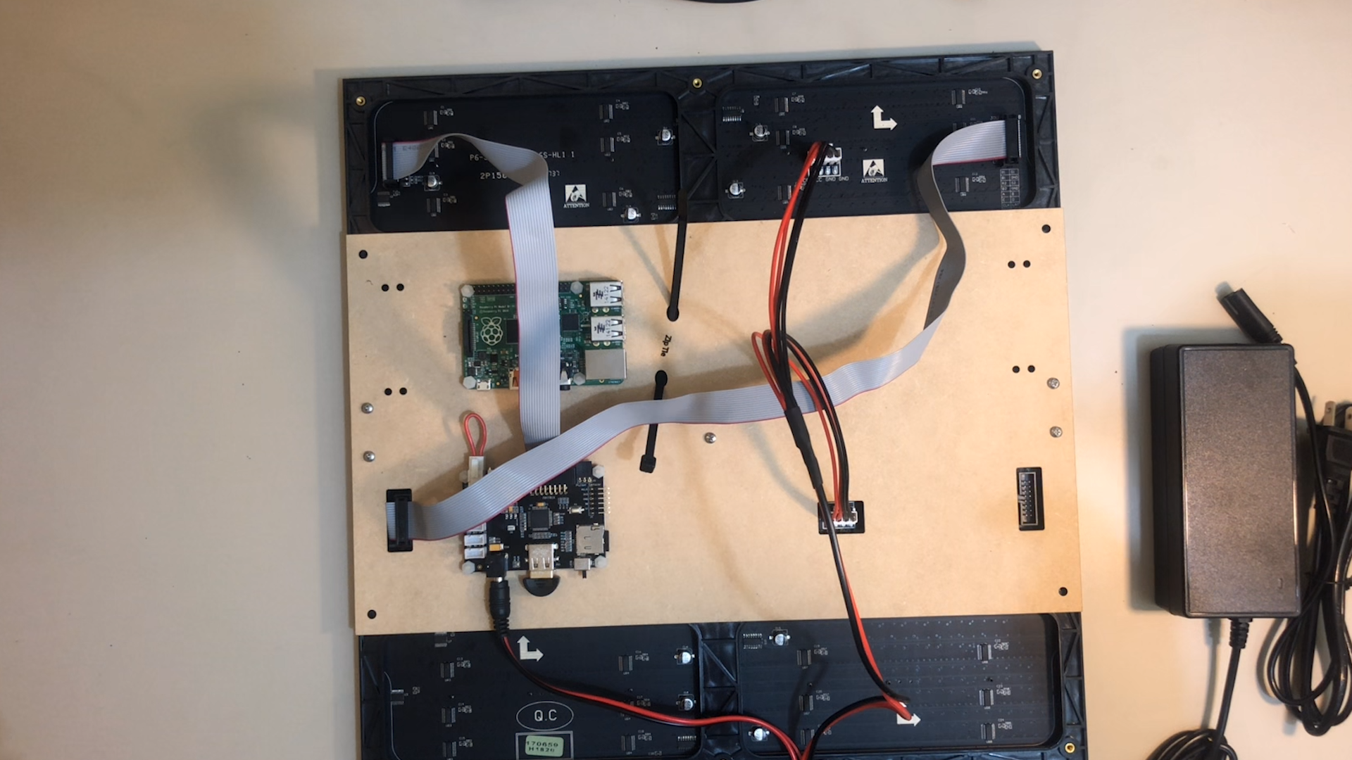 |
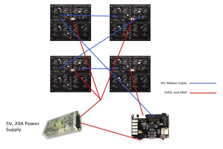
| Four 32x32s = 64x64In addition to the kit, you’ll need:4 IDC 16-pin ribbon cables (female connectors on both ends) at least 19″ long. and a 5V/20A power supply (see options below). The LED panels you purchase will come with the 4-pin LED power connectors. But you will need to splice the wires yourself per the wiring diagram.IMPORTANT: Follow the wiring diagram and ensure only one LED panel is getting power from the PIXEL board. | |
| Two 32x16s = 64×16 In this configuration, LED matrix power can go through the board. | 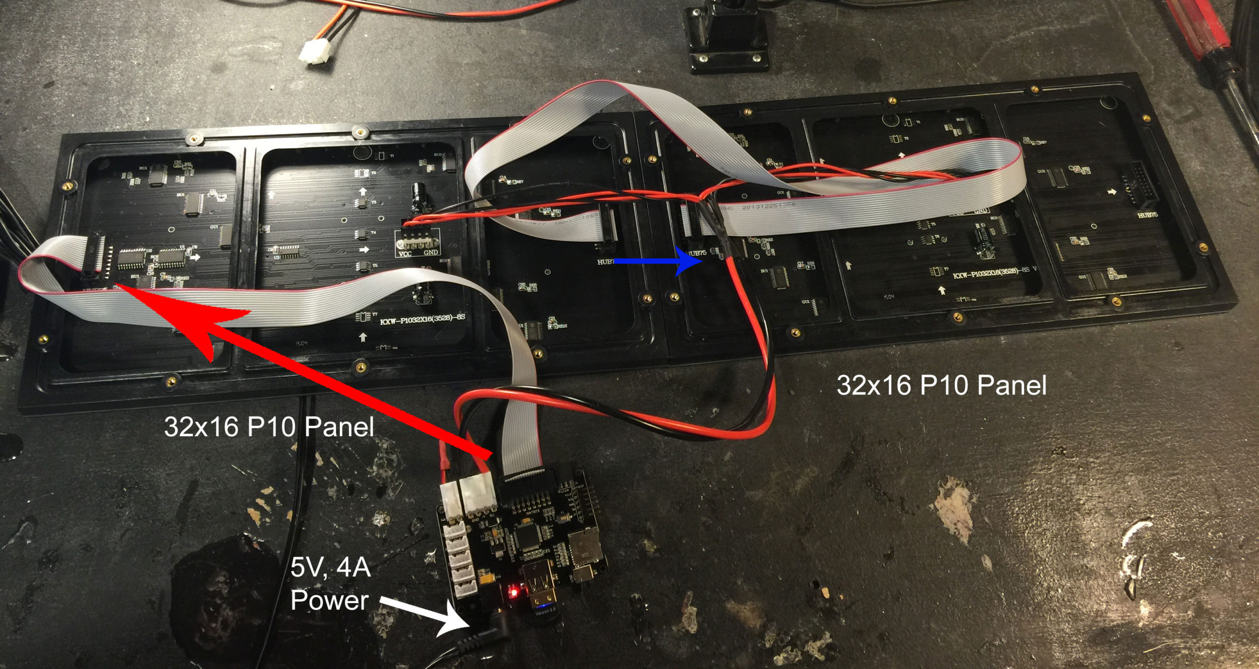 |
Recommended Power Supplies
| Power Supply | Vendor | Notes |
| 5V, 2A | Adafruit 5V, 2ASeeedstudio 5V,2A | |
| 5V, 4A | Adafruit 5V, 4A | |
| 5V, 10A | Adafruit 5V, 10A | |
| 5v, 15A | ALITOVE 5V, 15A | Do not supply power to the LED panels through the PIXEL board, see wiring diagram for 64×64 |
| Old PC Power Supply | Use the 5V rail, do not use 12V.Do not supply power to the LED panels through the PIXEL board, see wiring diagram for 64×64 |
Theory of Operation
Unlike Arduino based methods, IOIO differs in that the firmware is taken care of for you. You have full control of the IOIO pins from within your application code using the supplied IOIO Java-based libraries; no additional Arduino sketches are required! This significantly simplifies the process, allowing you to focus solely on your application code and not having to worry about any board/firmware code. The firmware is upgradeable using the IOIODude application from your PC over USB.
IOIO has an active community of users who can be found on the IOIO users forum.
The PIXEL LED Matrix IOIO board is a customized IOIO board specially designed for controlling a HUB75 LED matrix. The following IOIO pins are exposed on the PIXEL LED Matrix board via Grove ports. Grove is a 4-pin connector standard created by Seeedstudio allowing you to quickly plug in various Grove compatible sensors.
Open pins available for future expansion:
| Connector Type | IOIO Pins | Notes |
| Grove | 6, 35, 5V, GND | GPIO, 5V (optional alcohol sensor) |
| Grove | 4, 5, 5V, GND | GPIO, 5V |
| Grove | 31, 32, 3V, GND | Analog or GPIO, 3V (optional proximity sensor) |
| Grove | 33, 34, 3V, GND | Analog or GPIO, 3V |
| Grove | 1, 2, 5V, GND | I2C, 5V |
| 3-pin female | 36, 3V3, GND | Analog or GPIO, 3V |
| 6-pin male header | MCLR, 3V, GND, 38, 37. open | PICkit3 programmer interface |
The following IOIO pins are used for the LED matrix: 7, 10, 11, 19, 20, 21, 22, 23, 24, 25, 27, and 28